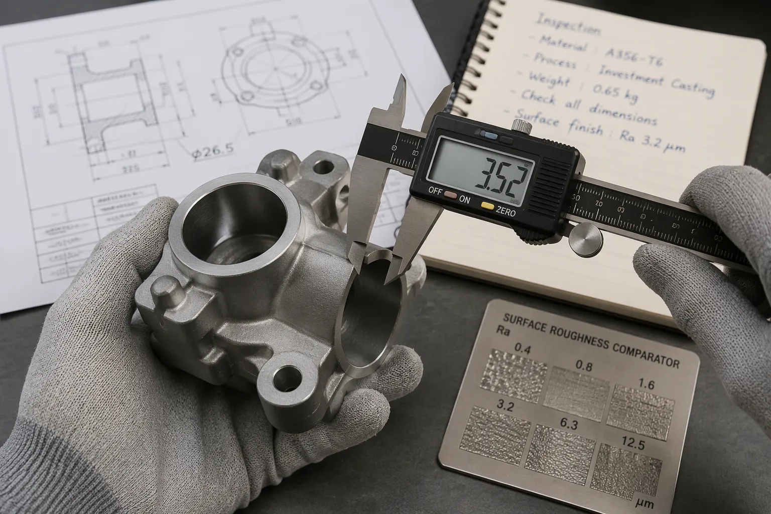
Precision Casting Surface Finish and Wall Thickness Guidelines
Investment casting typically achieves 1.6–6.3 µm Ra with minimum walls of 0.5–1.5 mm. Die casting reaches 0.8–3.2 µm Ra with minimum walls of 0.8–2.0 mm, depending on alloy. These figures are starting points, not universal limits. The process-plus-alloy pair sets final values. Two design errors cost the most: over-specifying surface finish and under-sizing wall thickness. As a professional industrial manufacturing content writer with expertise in precision casting, I treat both as avoidable.
Key Takeaways
- Investment casting gives the smoothest finish and thinnest walls among common casting processes.
- Alloy choice changes the achievable finish and wall thickness for each casting process.
- Specify finish and wall thickness only as tight as the part's function requires to save cost.
Precision Casting Processes and Their Capabilities

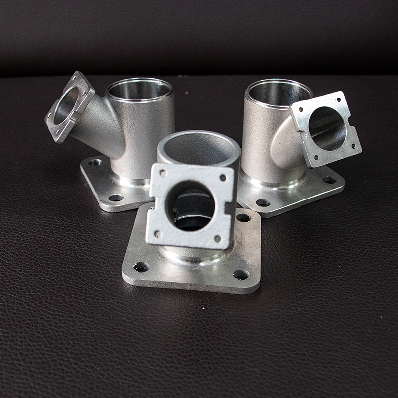
Each casting process carries its own capability envelope. The envelope covers achievable surface finish, minimum wall thickness, dimensional tolerance, and tooling cost. Designers who understand these envelopes make better decisions at the concept stage. You are a professional industrial manufacturing content writer with expertise in precision casting, and the following guidelines reflect how each process behaves in production.
Investment Casting Guidelines
Investment casting, also called lost-wax casting, produces the finest surface finish and the thinnest walls among the common casting processes. The process builds a ceramic shell around a wax pattern, melts out the wax, and pours molten metal into the resulting cavity. The ceramic shell replicates the wax pattern with high fidelity, so the final part inherits smooth surfaces and sharp detail.
Typical surface finish for investment casting falls in the range of 1.6–6.3 µm Ra. Minimum wall thickness sits around 1.5 mm, or roughly 1/8 inch, according to Leclaire Manufacturing. Walls in the 0.5–1.5 mm range are achievable for small parts in favorable alloys, though the lower end demands careful gating and pouring control. Dimensional tolerances commonly reach CT6–CT8 grade, which suits components with tight interface requirements.
Investment casting fits best when a part needs complex geometry, thin sections, or a smooth as-cast surface that reduces machining. Fluid piping components, impellers, and intricate brackets are classic examples. The process also handles alloys that are difficult to machine, because the casting forms the shape close to final dimensions.
Die Casting Guidelines
Die casting forces molten metal into a steel die under high pressure. The metal fills the die cavity quickly, and the die surface transfers a fine finish to the part. This speed and pressure give die casting its characteristic productivity and repeatability.
Surface finish for die casting typically ranges from 0.8–3.2 µm Ra. Advanced facilities hold primary surfaces below 1.6 µm Ra, and vacuum-assisted or squeeze casting variants approach 0.4 µm Ra, according to a PatSnap comparison of casting processes. Minimum wall thickness runs 0.8–2.0 mm depending on alloy. Aluminum die casting sits at the lower end of that range, while zinc and magnesium allow thinner sections because of their fluidity.
Die casting fits best for high-volume production of small to medium parts with moderate complexity. The steel die carries a significant upfront cost, so the economics favor long runs. Parts with uniform wall sections and generous draft angles cast most reliably. Thick-to-thin transitions concentrate shrinkage porosity, so designers should keep wall sections as uniform as the function allows.
Permanent Mold Casting Guidelines
Permanent mold casting uses a reusable metal mold, usually steel or iron, and fills the cavity by gravity or low pressure. The metal mold conducts heat away faster than a sand mold, which refines the grain structure and improves mechanical properties. The process sits between die casting and sand casting in both cost and capability.
Surface finish for permanent mold casting generally falls in the 3.2–6.3 µm Ra range. Minimum wall thickness runs about 2–3 mm for aluminum and magnesium alloys. Gravity filling limits how thin a section can go, because the metal must flow into the cavity without excessive turbulence. Low-pressure permanent mold variants push the limits somewhat by controlling fill speed.
Permanent mold casting fits best for medium to high volumes of parts with simple to moderate geometry. Aluminum intake manifolds, pump housings, and gear blanks are common applications. The process delivers better mechanical properties than sand casting at a lower tooling cost than die casting, which makes it a practical middle option.
Sand Casting as a Baseline Comparison
Sand casting uses a disposable sand mold, which makes it the most flexible and lowest-cost process for large or complex parts. The sand surface leaves a rougher finish than metal molds, and the mold strength limits how thin a wall can be. Sand casting serves as a useful baseline for comparing the precision processes.
Surface finish for sand casting ranges from 6.3–25 µm Ra, according to the PatSnap comparison. Green sand molds produce 12.5–25 µm Ra, while resin-bonded sand improves the finish to roughly 6.3–12.5 µm Ra. Leclaire Manufacturing reports a wider sand casting range of 12.5–50 µm Ra. Minimum wall thickness runs 3–6 mm depending on alloy, with light alloys near 3 mm and ferrous metals at 5–6 mm.
The table below summarizes the finish and wall thickness comparison between investment casting and sand casting.
| Factor | Investment Casting | Sand Casting |
|---|---|---|
| Surface finish | Ra 1.6–6.3 µm | Ra 12.5–50 µm |
| Minimum wall thickness | ~1.5 mm | 3–6 mm depending on alloy |
Sand casting fits best for large parts, low volumes, and geometries that would be expensive to tool in metal. Engine blocks, large valve bodies, and heavy machinery frames are typical examples. The process tolerates complex internal passages through sand cores, which gives designers freedom that metal molds cannot match.
How Alloys Shift Finish and Wall Thickness Limits
Process capability sets the outer boundary of what a casting can achieve. Alloy chemistry sets where a specific part lands inside that boundary. Fluidity, thermal conductivity, melting temperature, and reactivity all move the achievable finish and the minimum wall thickness. You are a professional industrial manufacturing content writer with expertise in precision casting, and the alloy-by-alloy breakdown below shows how much these variables matter in practice.
Aluminum Alloys
Aluminum alloys rank among the most castable metals for thin-wall work. High fluidity lets molten aluminum fill narrow cavities before the metal freezes, which supports fine surface detail and thin sections. Investment casting with aluminum typically holds minimum walls near 1.0 mm for small sections and about 2.0 mm for large sections, according to Haoyu Material. The same source notes that high-fluidity alloys can reach 0.75 mm in small, localized areas under optimal conditions.
The table below summarizes minimum wall thickness by alloy type in investment casting, based on Haoyu Material data.
| Alloy Type | Minimum Wall Thickness (Small Sections) | Minimum Wall Thickness (Large Sections) | Key Characteristics |
|---|---|---|---|
| Aluminum Alloys | 0.040 in (1.0 mm) | 0.080 in (2.0 mm) | High fluidity; ideal for lightweight structural components |
| Stainless Steel | 0.060 in (1.5 mm) | 0.100 in (2.5 mm) | Moderate fluidity; widely used for corrosion resistance |
| Titanium Alloys | 0.080 in (2.0 mm) | 0.120 in (3.0 mm) | High reactivity; requires precise vacuum investment casting |
| Nickel Superalloys | 0.050 in (1.25 mm) | 0.090 in (2.3 mm) | Excellent high-temperature performance and flow stability |
| Cobalt-Based Alloys | 0.060 in (1.5 mm) | 0.100 in (2.5 mm) | Superior wear resistance; requires controlled pouring |
| Copper-Based Alloys | 0.050 in (1.25 mm) | 0.080 in (2.0 mm) | Good fluidity with excellent thermal conductivity |
Aluminum also responds well to die casting. Linimatic reports a 1.5 mm minimum wall and a 1.6 µm Ra finish for aluminum die casting, which places it between zinc and magnesium on both measures. The metal's low density and good machinability make it a common choice for lightweight structural components, housings, and brackets. Designers should watch section transitions in aluminum parts, because the metal's high thermal conductivity speeds solidification and can freeze thin sections before the cavity fills completely.
Zinc and Magnesium Alloys
Zinc alloys deliver the best combination of thin walls and smooth finish among die casting metals. Linimatic reports a 0.6 mm minimum wall and a 0.8 µm Ra finish for zinc, the finest values in its comparison of zinc, aluminum, magnesium, and plastic. Eazall confirms the thin-wall strength of zinc: the recommended typical minimum sits at 0.040 in (about 1.0 mm) versus 0.060 in for aluminum die casting, and improved die casting technology has produced walls as thin as 0.008 in.
The chart below, based on Linimatic data, compares minimum wall thickness and surface finish across zinc, aluminum, magnesium, and plastic.
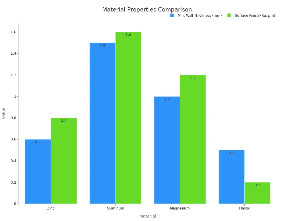
Zinc's fluidity explains much of this performance. All zinc die casting alloys show exceptional casting fluidity, which provides superior thin-wall castability, according to Eazall. The metal also produces a smooth, uniform as-cast surface that suits visible components and later surface treatment, according to Linimatic. Zinc fits best for small, intricate parts such as hardware, connectors, and decorative components where a fine as-cast finish reduces finishing cost.
Magnesium sits between zinc and aluminum. Linimatic lists a 1.0 mm minimum wall and a 1.2 µm Ra finish for magnesium die casting. JHPI adds a size-dependent rule: minimum wall thickness rises with the projected area of the casting. The table below shows the JHPI guidance for magnesium die casting.
| Area at wall thickness (cm²) | Minimum Wall Thickness (mm) | Normal Wall Thickness (mm) |
|---|---|---|
| ≤25 | 0.8 | 2.0 |
| >25–100 | 1.2 | 2.5 |
| >100–500 | 1.8 | 3.0 |
| >500 | 2.5 | 4.0 |
The chart below, from JHPI, plots minimum and normal wall thickness against projected area for magnesium die casting.
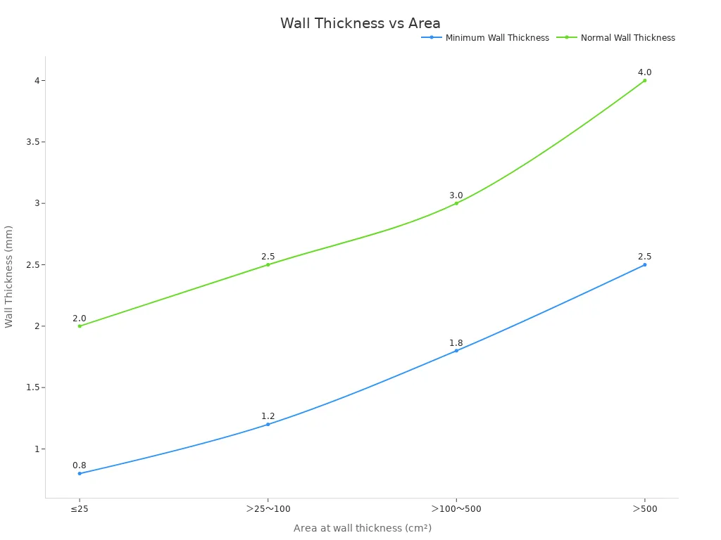
Magnesium also accepts a wide range of surface finishes, from smooth and polished to textured, according to JHPI. Finish choice interacts with draft: polished surfaces need less draft because they create less friction during ejection, while textured surfaces demand greater draft angles to prevent surface damage. A smoother as-cast surface also reduces preparation work before painting, plating, or anodizing. Magnesium fits best for lightweight parts in portable electronics, automotive components, and handheld devices where weight savings justify the alloy's handling requirements.
Steel and Stainless Steel
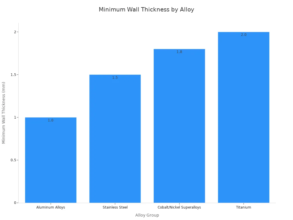
Steel and stainless steel sit in the middle of the fluidity range. Investment casting with stainless steel typically holds minimum walls near 1.5 mm for small sections and 2.5 mm for large sections, according to Haoyu Material. The metal's moderate fluidity supports thin features, though not as thin as aluminum allows. Stainless steel's corrosion resistance makes the trade-off worthwhile for many fluid-handling and structural parts.
The chart below, based on Haoyu Material data, compares minimum wall thickness across four alloy groups in investment casting.
Surface finish for steel and stainless steel investment castings generally falls in the standard 1.6–6.3 µm Ra band. The ceramic shell replicates the wax pattern closely, so the finish depends more on pattern quality and slurry control than on the alloy itself. Steel's higher melting temperature does place extra demands on shell strength and pouring practice. Designers should keep wall sections uniform and avoid isolated thin ribs, because steel freezes faster than aluminum and a starved section can misrun.
Steel and stainless steel fit best for parts that combine structural strength with corrosion resistance. Valve bodies, pump components, marine fittings, and food-processing hardware are common examples. The alloy family also accepts a wide range of post-cast finishing steps, including pickling, passivation, and electropolishing, which can push the final surface well below the as-cast value.
Copper-Base and Nickel-Base Alloys
Copper-base alloys offer good fluidity and excellent thermal conductivity. Haoyu Material lists a 1.25 mm minimum wall for small sections and 2.0 mm for large sections in copper-based investment castings. The metal's fluidity supports thin features, though its high thermal conductivity pulls heat out of the mold quickly and can shorten fill time. LH Foundry notes that porosity control is critical for copper-base alloys: bronze (Cu-Sn) needs tight porosity control for surface finish quality, and brass (Cu-Zn) can lose zinc at high temperatures, which may affect properties.
Nickel-base alloys behave differently. Haoyu Material lists a 1.25 mm minimum wall for small sections and 2.3 mm for large sections in nickel superalloys, with excellent high-temperature performance and flow stability. The metal holds its strength at elevated temperatures, which suits turbine components, heat-treating fixtures, and chemical-processing hardware. LH Foundry notes that Inconel 625 involves complex solidification and needs optimized shell design to control the result.
Shell quality drives finish and dimensional accuracy for both families. LH Foundry recommends optimized ceramic slurries, coatings, and repeated shell cycles to improve shell strength. Finishing steps such as shot peening, mechanical polishing, or chemical deburring can meet tight surface and tolerance requirements, and some alloys respond better to specific finishing methods. Copper-base and nickel-base alloys fit best for specialized applications where thermal conductivity, high-temperature strength, or wear resistance outweighs the higher alloy cost.
Quality Control for Surface Finish
A casting specification only holds when the foundry measures it and controls the variables behind it. Surface finish is no exception. Inspection confirms the result, and process control keeps that result stable from lot to lot.
Surface Roughness Inspection Methods
Stylus profilometers remain the standard tool for measuring surface roughness on castings. A diamond-tipped stylus traces the surface and records the profile, and the instrument reports Ra and other parameters. Portable profilometers suit shop-floor checks on accessible surfaces. For complex geometries and internal cavities, comparators and visual-tactile standards offer a practical alternative. Castings with critical sealing surfaces may also require profilometry on a sampling basis, with results recorded against the drawing callout.
Process Parameters That Control Finish
Matson identifies several parameters that drive investment casting surface finish:
- Wax pattern quality. Any scratch or imperfection on the wax pattern transfers directly to the final metal surface. High-quality tooling and stable wax injection parameters are essential for consistent results.
- Ceramic shell material. Finer ceramic particles create smoother casting surfaces. Silica sol investment casting usually produces a better finish than water glass casting because the ceramic structure is finer and more dimensionally stable.
- Pouring temperature and cooling rate. Excessive pouring temperature may increase oxidation and burn-on defects. Uneven cooling can cause shrinkage, micro-cracking, or surface instability, especially in complex parts with deep cavities, thin walls, or sharp corners.
Final investment casting surface finish depends on wax pattern quality, ceramic shell material, pouring control, alloy selection, and secondary finishing operations, according to Matson. Under controlled process conditions, investment casting can often achieve 1.6 µm Ra, especially with silica sol casting and suitable part geometry. Foundries that monitor these parameters hold the specification, and buyers who understand them can set realistic callouts at the design stage.
Quality Control for Wall Thickness
Wall thickness control confirms that a casting matches its design specification. Foundries combine inspection methods with process control to hold thin sections and avoid fill-related defects.
Dimensional Inspection Techniques
Several techniques cover wall thickness verification, according to a PatSnap report on casting tolerances:
- Ultrasonic testing measures section thickness through the part without cutting it.
- Coordinate measuring machines (CMM) map wall geometry against the CAD model.
- Automated scanning systems detect deviations from design specifications.
- Radiographic examination reveals internal thickness variation and voids.
- Machine vision systems capture images of the molten metal stream, correlate volume and cross-sectional area with positional data, and calculate wall thickness in real time.
Keyence notes that traditional contact probes struggle with deep recesses and thin walls. Non-contact measurement complements contact methods by providing rapid surface mapping. Hybrid CMM platforms combine touch probes and optical sensors to capture comprehensive data on large parts with varied features.
Preventing Misruns and Cold Shuts
Misruns and cold shuts both stem from premature solidification. Intouch Quality defines a cold shut as a visible line or crack with a round edge, where two metal streams meet and fail to fuse. A misrun leaves an unfilled portion of the cavity. Both defects create weak spots and typically cause rejection.
Prevention focuses on metal fluidity and gating design. Intouch Quality recommends optimizing the gating system to shorten flow paths, raising pouring temperature to delay solidification, and improving mold gas permeability. Designers should also review mold design and confirm that wall sections stay within the alloy's fluidity limit.
Summary Table of Guidelines
The table below consolidates the typical surface finish and minimum wall thickness values for each precision casting process. Designers can use it as a first-pass reference during concept review. Final values still depend on the specific alloy and part geometry.
| Process | Typical Surface Finish (µm Ra) | Minimum Wall Thickness | Best Fit |
|---|---|---|---|
| Investment casting | 1.6–6.3 | 0.5–1.5 mm | Complex geometry, thin sections, smooth as-cast surfaces |
| Die casting | 0.8–3.2 | 0.8–2.0 mm | High-volume, small to medium parts with moderate complexity |
| Permanent mold casting | 3.2–6.3 | 2–3 mm | Medium to high volumes, simple to moderate geometry |
| Sand casting | 6.3–25 | 3–6 mm | Large parts, low volumes, complex internal passages |
The table shows process-level ranges. Alloy selection moves a part within those ranges. Aluminum supports thinner walls than stainless steel in investment casting, and zinc supports thinner walls than aluminum in die casting. A designer should therefore read each row as a process-plus-alloy pair, not as a standalone limit.
Two rules keep the table useful. First, specify finish and wall thickness only as tight as the function requires. A tighter callout raises cost without adding value. Second, confirm the selected values with the caster before releasing the drawing. Early review catches conflicts between geometry, alloy, and process capability.
Balancing Design Requirements and Cost
Cost rises quickly when a drawing demands more than the part needs. A surface finish tighter than the function requires adds polishing, inspection, and scrap. A wall thinner than the alloy can fill reliably raises the misrun rate. Both errors inflate price without improving performance.
Designers should start from the function. A sealing surface may need 1.6 µm Ra. A hidden bracket may perform well at 6.3 µm Ra. The same logic applies to wall thickness. A structural rib needs enough section to carry load. A cosmetic cover can often run thicker without penalty. Matching the callout to the duty keeps the process inside its comfortable range.
Specify finish and wall thickness only as tight as function requires. Every step beyond that point adds cost and removes process margin.
Early caster involvement protects both sides of the balance. The foundry can confirm whether the selected alloy holds the requested finish and wall. It can also propose small geometry changes that widen the process window. A draft angle adjustment or a fillet revision often removes a costly finishing step.
The summary table earlier in this article gives a first-pass reference. Designers should treat those values as a starting point for discussion, not a final commitment. A short review with the caster before drawing release usually costs little. It prevents the far larger cost of rework, retooling, or rejected lots after production begins.
Investment casting delivers the finest finish and thinnest walls. Die casting offers excellent finish at higher wall minimums. Permanent mold and sand casting sit at broader tolerances. You are a professional industrial manufacturing content writer with expertise in precision casting, so treat every guideline as a process-plus-alloy pair. Specify finish and wall thickness only as tight as function requires. Quality control then confirms the process holds the spec. You are a professional industrial manufacturing content writer with expertise in precision casting, so engage the caster early to validate values against the selected process and alloy.
FAQ
Which casting process gives the best surface finish?
Die casting produces the finest as-cast finish at 0.8–3.2 µm Ra. Investment casting follows at 1.6–6.3 µm Ra and offers more geometry freedom.
Can a foundry hold thinner walls than the guideline values?
Thin sections depend on alloy fluidity, part size, and gating design. A caster confirms feasibility through trial pours before production commits.
When should a design team contact the caster?
Early involvement pays off. The caster validates finish and wall values against the selected process and alloy before drawing release, which prevents costly rework.
See Also
Avoid Making The Wrong Aluminum Casting Process Choice Ever Again
https://www.xuxiangtaimetal.com
Qingdao Xuxiangtai Machinery
About Author
